| Wyvern Semiconductors | Expert in Digital IP Solutions |
|
JPEG IP Development Process (incomplete)
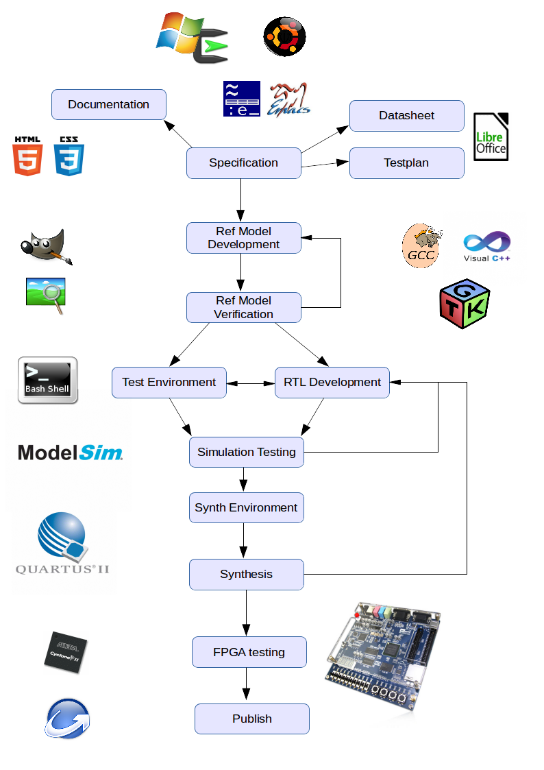
IntroductionThe development flow adopted for the JPEG decoder IP is based on developing a C model decoder, and using this as a reference to verify the HDL implementation, before targetting the IP at an FPGA development board, and verifying operation at full speed. For the most part, the tools used, for both software and hardware development are available at no cost, but are editions of the full commercial products, such that all the development described is relevant to commercial tool flows. The major cost incurred in implementing the processes described in this article was for the FPGA development board, at a list price of around $150. Some additional costs for cabling were also incurred, but the whole development was less than $200 (access to a PC is assumed). Therefore, in this article it is hoped to show a complete digital IP development flow from start to finish, covering the major processes of such a development (though not all—there are many additional requirements if targetting the IP at an ASIC), which can be repeated or adapted by others for a minimum of financial outlay, whilst producing IP to a high level of quality assurance. An overview of the development flow is shown below:
The diagram shows a simplified designed flow, but attempts to give a general appraoch used for most IP developments. Alongside the major steps are some graphics to indicate what tools might be used at each state (see Third Party CAD tools section) The heart of the process is the specification. This is vitally important, as everything else hang off of this document. It is, of course, possible, to have a specification 'in mind' when developing IP, but if a project is being developed by multiple designers (possibly at multiple sites), and is complex, with multiple complex sub-units, it would be all but impossible to develop a design without this common reference. Depending on the project complexity, the specification may just be list of requirements or desired features, or it may specify the top level architecture and detail the interfacing between the sub-blocks and other more detailed requirements. From this, all other documentation follows, such as a datasheet, listing only those external feeature relevant to a user. Internal design documentation also needs to be consistent with the specification, documenting how how the implementation achives the requirements. A key document that flows from the specification is the test plan. At a fundamental level, this is a checklist of all the functional requirements from the specification, that can be cross-referenced with individual tests, or sets of tests. This is key to ensure that all functionality is covered. The document may also include more details on the means of testing, environment details, required tools and intended usage information. Once the specification is settled, then implementation begins. In reality, and not shown in the simplified diagram changes to specification may occur during the implementation phase. This could be because requirements change from the end customer, or through unanticipated limitations to implementations, discovered only after having started, or even due to schedule constraints—only a sub-set of functionality can be achieved within the given timescales, and is more acceptable than failing to deliver on-time. A multitude of reasons may occur. For our purposes, let's assume the specification is finalised. For JFIF, a reference C model is implemented, and is the heart of verifying the HDL implementation. The code is compiled with the GNU C/C++ tool chain, and also has an MSVC solution defined. Both gdb and the MSVC IDE were used in debugging. Verification consists of a set of directed tests, with files containing all pertinent cases, and also of passing through a very large number of random JPEG files. Many of the directed test files were picked from files that originally failed from the random list, in order to verify that the fix placed i nthe code did not regress with subsequent changes and updates to the model. Other files were generated via the GIMP application, where many options are available when saving to JPEG format that control desirable features of the test image; e.g. Quantisation tables, DRI frequency, standard or optimsed Huffman tables, colour or greyscale, sunsampling options etc. Verifying the contents of the test files, before the model was fully working was greatly aided by the use of JPEGsnoop, which allowed access to all information of the encoded data, for comparison with the model. These are specific to the JFIF project, but the general philosophy for this point of the process, is the need to have means to generate test data and a way of verifying the validity of the output, perhaps by a know good reference, or some other constructed means to generated expected values. This maps to the HDL verification as well. In JFIF's case, the reference model then becomes the expected value generator, but other means might be more relevant to other projects. For instance, third part vendors can provide Verification Intellectual Property (VIP), particularly for standardised functionality. An example is a USB bus-functional model and monitor (from Synopsys and others), where input stimulus can be generated by the BFM and output reponses checked by the monitor. Obviously implementation and verification of the model is an iterative process. It is extremely unlikely that one can code the entire model and generate all the test vectors, and have everything work by running the vectors through the model just one. In practice, one implements some of the basic functionality, ans the means to exrecise it, and then tests and ebugs this before adding more advanced functionality. This process iterates until all testing requirements are met. This will also be true of the HDL verification. Indeed it is not unreasonable to expect that an issue in the model will not be highlighted during testing of the HDL, and require going back to the model implementation and debug stage. This highlights another philosophy in the verification strategy, in that by having two separate implmentations of the functionality (in this case the model and the HDL) it becomes very unlikely that they will have the exact same defect in both models—but the reference could still be the one that does not conform to the specification. In ideal development circumstances, the reference and the HDL would be constructed by different parties. There is still a danger that wrong interpretations or assumptions can be model by the same group or individual if both implementations come from the same source—testing for self-consistency is much easier than testing for compliance (but not very useful). Synthesis for JFIF consists of wrapping the core in code to interface to the FPGA pins, along with ancilliary module instansiation, such as PLLs for clock generation. A set of design constraints is required to tell the synthesiser what the clock frequencies are and what the timing requirements on the inputs and output pins are. For JFIF this is all fairly simple, with a single clock domain, and the I/Os treated as asynchronous. In more complex, multi-clock designs, more elaborate constraints are needed to defined the design, inculding false-path definitions between unsynchronised sections of the design, that cross the boundaies between them. When running the Quartus II tool, the flow automatically moves on from synthesis (called mapping in Quartus) to place-and-route (called fitting). Timing is checked in another step—static timing analysis (STA) to report whether the mapping and fitting produced a solution that can run at the frequencies specified in the constraints, and meet the I/O timing specs. If timing is not met, then the implementation will need to be changed to give the same functionality as before, but to reduce timings on 'critical paths'. It is well beyond the scope of this article to look at strategies for doing this, and the problem is not a trivial one. It involves both awareness of the likely limitations of the target for the given frequencies (i.e. how much can be done in one clock cycle) whan initially implementing (this comes with experience) and techniques for refactoring a design (e.g. cycle stealing). The final step of the Quartus II flow is to generate (assemble) a configuration file for the FPGA. This is (very loosely) equivalent to 'tape out' or 'pattern generation' in an ASIC flow; i.e. generation of data suitable for the foundary that will manufacture the ASIC. A lot, lot more is done before tape-out that is not covered in the JFIF FPGA flow. Production test vectors need to be generated, gate level simulation would almost certainly have been done, and formal verification between the generated (or possible modified) netlist against the original RTL—and much, much more. For JFIF, the final step is to make the IP available. This utilised the Inno Setup tool which allows a set of files to be bundled in a single executable package. This isn't really part of a standard flow, but was done for JFIF, and various other mean can be employed if IP is to be made available. Of course, if making an ASIC, it may be that the source is not be be published at all. Specification and FeaturesIncluded FeaturesBelow is listed a sketch specification for the JFIF decoder. The overall objective for the specification is to support decoding of all baseline JFIF files, and some baseline variants of JPEG.
The specifications is set to not limit the size of JFIF/JPEG files that can be decoded, which dictates that the design cannot hold an entire svan within its internal buffering. This implies that the design must be pipelined, and be able to be stalled. Some internal buffering cab employed at the granularity of MCUs (8x8 matrices). The SOF0 support is for baseline encoded images, which constitute the vast majority of the images encountered—certainly those sample from the 15000 or so used in verifying the reference model. Both greyscale and colour images are supported. Some files have been seen to be RGB rather than YCC encoded, and the reference model supports these. This is not yet specified for support in the JFIF decoder. All normal sub-sampled files are to be supported. An exception is the veritcally sub-sampled 4:0:0 encoding— the code can support this, but this is not yet specified for verification, and is an optional feature. Multiple ECS scan support is required. The DRI reset interval segment must be supported, but the actual resets of the DC values is to be a function of the RSTx codewords only. Thus, if a mis-match between the DRI interval and the actual encountering of a RSTx marker do not tally, this should not cause a failure, or an error code. Also the ordering of RSTx markers is not to be checked, and out-of-order sequences shall not cause an error. Additional robustness is to be implemented in allowing any order of header segments between SOI and SOS, regardless of JPEG or JFIF specifications. The SOS must be followed by the scan data, and terminated with and EOI marker. There is no specification for automatic recovery from missing EOI, and external logic will be responsible for recovery, and the resetting of the core. The core can skip over and ignore any APPx and COM sections. (Optionally APPx segments can have internal data decoded, if desired.) All unrecognised segments shall flag an error, as shall all unsupported segment types—each with a separate error code. The input interface shall consist of a 32 bit (4 byte) interface, with a unary byte valid input, and a returned, single bit acknowledge. Data is transferred only when both a valid bit is set and the acknowledge bit is set. An individual image decode (from SOI to EOI) must be presented to the core 4 bytes at a time, until the last word transfer, where less than 4 (but contiguous) bytes may be transfered. The output interface is an 8 byte interface, with a single bit valid output, with a single bit acknowledge returned. Data is transfered only when the valid and the acknowlege signals ar active. The data transferred is always 8 bytes. A set of consecutive 8 byte transfers constitute an MCU. For colour (YCC) images, the data is one or more luminance (Y) MCUs (depending on the sub sampling) followed by the Cb and the Cr MCUs in that order. Each 8 byte output within an MCI is a column, starting from column 0 and incrementing. The byte order within a column is byte 0 (bits 70 downto 0) containing row 0 byte, through to byte 7 (bits 63 downto 56) containing row 7 byte. Header information must also be available at the core top level for use in subsequent colour decoding of the output data, and positioning in an image buffer. These shall consist of a 144 bit SOF output interface and a 72 bit SOS interface. The bit ordering of these two vectors is not defined in the specification (implemented bits are defined in rtl/verilog/jfif_extract_hdr.vh). Any other internal state suitable for external visibility, such as FSM state, may be added to the core's ports. Which state is brought to the core's edge is not specified here. Internal error detection shall be flagged on an external port. The catagories of error that shall be reported are:
When any of the above errors are encounted a non-zero error code shall be reported on an external port (zero shall be reserved for 'no error'). When an error is encountered the core shall halt in an error state until a 'clear error' input is set, and then cleared, when the core shall resume searching for a new image—i.e. gobbling input data until a new SOI marker is encountered. The core will have fully synchronous operation, in a single clock domain. The core shall be reset with a single, active low, asynchronous reset input. The clock rate shall be a minimum that allows 1080p HD colour frames, with no sub-sampling (3 bytes per pixel), at a rate of 25 frames per second: 1920×1080×3×25/(4 bytes per clock) = 38.88MHz. Unsupported Features
Third Party CAD toolsFigure 13 has, annotated to the flow diagram, logos representing examples tools used for the various stages. For example, at the top is shown the logos for windows with Cygwin, or Ubuntu as an alternative (both used in JFIF), as the major operating system for the deveopment. An editor is also going to be needed, such as Emacs (or in JFIF's case Xvile)—any editor would do. In JFIF, the documentation (such as this page) is HTML with CSS3, and the diagrams were created with Libre Office. The reference model was coded in C++ (and some C) using both GNU gcc (and g++) Micorsoft Visual C++, and the GTK+ library was used. Creating test JPEG files was via various sources, but GIMP was used for many of the directed test files. The JPEGsnoop utility was an enormous aid in debugging code and checking test files. Once the reference model is verified, development of the HDL takes place, along with the verificatoin environment. The test environment for JFIF involves using bash shell scripts, through other languages would probably be used for more sophisticated test platforms, such as Python or Perl. Simulation of JFIF was done exclusively on Modelsim, though NC-SIM or VCS would also be suitable. As JFIF was targeted at a Cyclone II device, Altera's Quartus II is used for synthesis, with automatic place and route. For an ASIC flow, the synthesis might be using Synopsys' Design Compiler, targetting an specific vendor library ofr a given geometry (e.g. 90nm). The place and routing is is a separate step, and way more complicated than for an FPGA, and involves additional features in the design to allow for the production testing of the circuits. Once all the final design is synthesised, the Cyclone II FPGA on the development board can be configured, and full speed testing can begin. The release of the source code, for JFIF, was via the Inno software. What follows is a list of the tools used in the development of the JFIF project, and some instructions for obtaining and installing them. The idea here is provide enough information to replicate fully the results of the JFIF development, and have all the tools available to further develop this project. For the most part the discussion assumes a Cygwin environment on a Windows platform, as the majority of the development was done with this setup. However, the project has been tested under a linux environment (using Ubuntu 12.04LTS), and some notes are included for this to allow those wishing to use this operating system to do so. The following table is a list of all the components, software and tools used during the development.
It is not essential to have all the tools listed above to compile and run the JFIF package as delivered. As a minimum, however, then some basic tools are needed. If running under Cygwin, then Cygwin must be installed, with gcc/g++ and GTK+. Then the windows editions of Modelsim and Quartus II must be installed, and your Cygwin environment updated to point to the binaries of this tools. This will allow a full regresion run and synthesis of the JFIF project. For Linux, the situation is very similar, except the linux versions of the tools must be installed, and the OS a suitable linux version—Ubuntu12.04LTS has been verified, but a RedHat or similar is very likely to work with little trouble. If wishing to load and run on an FPGA board, the the DE1 and cable are the configured and tested units, but the project can be adjusted to target other FPGAs and development boards, though al lot more work is required if not an Altera based board. For the windows/Cygwin environment. Microsoft visual C++ express is an alternative to compiling the reference model. In this case, GTK+ must be available and configured for windows (and not just Cygwin), or the model must be compiled with JPEG_NO_GRAPHICS defined when compiling. The resultant executable would have to be copied to the sw/jpeg_cpp/build directory, as the other scripts expect a model executable in this location. This is more useful if the reference model is of interest stand-alone, as if Cygwin is environment, one may as well let the build scripts use gcc/g++ and place the results in the expected places. As mentioned above, the GTK+ libraries and development headers are required by default, and should easili be cpnfigured for Cygwin (or Linux). If there are issues with this, then defining JPEG_NO_GRAPHICS when building the reference model (by updating the makefile or MSVC Preprocessor Definitions) removes the graphical capabilities, which are not used in the automatic regression flow. Therefore GTK+ is not absolutely essential, but is recommended, to avoid unnecessay work. The coverage tools LCOV and GCOV are not essential tools, but were used to give a measure of the test case coverage of JFIF functionality. With good coverage on the model for the test cases used, then good coverage on the HDL is acheived by running the same cases through the hardware (in simulation) and bit-matching against the reference. A 100% coverage, though, does not guarantee full functionality, and these tools were used specifically to check that not functionality was uncovered. As a collegue once said to me—is just to ge a "warm feeling". There is still lots of testing that would need doing. Calvin Hass's JPEGsnoop tool is not essential, but was used extensively in the development of the JFIF project. It is a fantastic utility for exploring the details of a JPEG file, and proved invaluable as a debug aid. If you plan to modify the code, you would do well to have this tool available. It is ony for the windows environment though—and I haven't tried it under wine as yet. The GNU Image Manipulation Program (GIMP) is another non-essential tool, but was a useful application for generating JPEG files of various characteristics from source bitmap files. When exporting to JPEG format, the tool gives various options that allow generation of quantisation tables of varing compression/quality, all the subsampling options and various forward DCT generation. Other tools can probably do the same thing (e.g. Adobe Photoshop), but at least GIMP is free of charge, and a Linux version is available. Finally, the Inno setup tool was only used to package up the project into a self-extracting executable (windows only). If you're not planning to re-release modified code (under the terms of the licenses) then you probably don't need this. It is easy to use, however, and a powerful way of packging up source files etc. As well as the tools mentioned above, additional programs, programming languages and scripting languages were used in the JFIF project, that are standard in the Cygwin and Linux environments. The heart of compiling and running the various stages of the project is the GNU 'make' program, and various makefiles are used throughout the project, with a top level makefile in "sim/rtl/run". This makes uses of various scripts which have deliberately been restricted to BASH shell scripts. The required sophistication of the scripts was not high, and the BASH shell is ubiquitous in the Linux based environments. The use of Perl or Python was not warranted, would be overly complex and suffers (to varying degrees) on version incompatibilities. As a main objective of this project is as a teaching reference, adding this level of complexity for no functional advantage would counter this objective. The reference model is written in C and C++ and, though the teaching of these programming languages is not a goal of the project, it serves as a reference point for these languages. Speed of execution is also a factor for the reference mode (though not an overriding one, where accurate modelling of h/w architecture takes precedence), and so a compiled language was chosed over a scripting or interpreted language. C and C++ is very standard and portable, making it ideal. Package StructureThe diagram below gives a hierarchical view of the delivered JFIF package to aide in navigation around the various files and directories. The directory structure is based on that defined by the OpenCores organisation (see the OpenCores coding guidelines document). Unfortunately, the project was started before being aware of these guidelines. The HDL is compliant around 90% of the guidelines. The main violations is the naming of port signal direction, where these are prefixed in JFIF, but the guidelines specify suffixes. At some point, it is likely that the HDL will be updated to meet these requirements fully.
The package is divided into several convenient sections. All the documentation (including this document) can be found under doc/. Copies of the ITU and JFIF specs can also be found there. The decoder core HDL design is under rtl/. As this is all written in verilog, all the code is under a verilog/ sub-directory. The started edition of Modelsim and Quartus do not support mixed language modes, and so all RTL and testbanch behavioural code is in a single language (verilog). Which brings us onto the verilog for the testbench under bench/. This is a single top level file, with a header. RTL simulation files are under sim/rtl. This includes all the scripts (sim/rtl/bin) and makefiles (sim/rtl/run) needed to comile and run tests. Most standard activities associated with compilation and the running of tests should be executed from sim/rtl/run/, using the makefile provided. Synthesis can also be invoked from here. The software directory (sw/) contains all C/C++ source code used for verification, including the C reference model, and the utilities. The model files are housed in jpeg_cpp, and the utilities under hex2rgb. Each sub-directory has its own makefile, but these can be accessed via the sim/rtl/run/ makefile. The reference model directories is also where all the directed test imagaes are kept (sw/jpeg_cpp/test), as these are common to both testing the reference model and the HDL. The refence model source code and compile scripts all reside here, and the sw/jpeg_cpp sub-directory can be separated as a complete stand-alone package, if only a software implementation is of interest. The final directory, syn/, if for HDL synthesis. As only Altera FPGA synthesis is currently supported, a sub-directory (syn/altera/) houses the project and settings files etc. A verilog wrapper is defined in syn/altera/src/. Currently this is just for Timing closure purposes, and not for targetting the development board. A makefile is provided dor synthesis compilation, which can also be accessed from the sim/rtl/run makefile. Verification EnvironmentTop Level VerilogUtilitiesScriptsReference ModelCompilation and ExecutionThe JFIF project uses GNU make to compile and run all its elements. There is a hierarchy of make files, such that individual components, like the reference model, or the synthesis of the FPGA image, can be made. However a top level make file is constructed which give access to building all the individual components, suitable for almost all needs. The make file is located in sim/rtl/run. By changing to this directory and typing 'make' a help message is displayed giving information about the various options. The table below shows the details of these options.
Starting with the top option 'run', this is used for running an individual RTL simulation. Various options are available to select the input JPEG test file (INPUTFILE), the simulation HEX output file (HEXFILE) and the bitmap file (BMPFILE) target when converting the hex data. By default the simulation will run in batch mode, but by setting GUI=yes the simulation will fire up the GUI window and run the simulation there, for debug. The simulation environment is controllable via several PLUSARG options. These can be passed to the simulations by setting PLUSARGS to a single string containing all the relevant plus options. Executing a 'make run' will also invoke a compilation of the reference model, the utilities and the simulation. The make process will display little output when running, unless an error occurs, and normally simply returns with any messages. This is fine unless an error occured in one of the steps (particularly in a sub-make build), where it might be handy to know at what point in the process the error occured. By setting VERBOSE=yes, all messages regarding changes of directory and the simulation compile messages etc., are enabled allowing ease of debugging. The VERBOSE option is common to almost all the make targets. If only a simulation compilation is required, then 'make compile' is used. By deafult, this is a full compilation, to ensure complete coverage. Hwoever, with INCR=yes set, then an incremental compile is invoked. Compiling te simulation will also compile the reference model and the utilities. These can also be compiled separately with 'make ref_model' and 'make utils'. To run a complete regression test of the directed test cases, 'make regression' is used. In order to ensure that the regression run is definitely using the latest source code, a clean is performed, followed by a full build of the simulation, as well as the reference model and the utilities, before the tests are run. A pass/fail message is printed at the end of the regresion run, but a log is generated in sim/rtl/log/regression.log for post-test inspection, as well as logs of the individual test runs. To compile the core for the FPGA, 'make synth' is run. This causes the makefile in syn/altera to be invoked, which is a batch compilation consisting of the four main stages of the synthesis: mapping, fitting, static-timing and assembly. The syn/altera directory will contain all the Quartus II output data, where individual reports may be inspected, or the GUI invoked on jpeg_decoder.qpf, and the design results explored through this. Two levels of cleaning are provided in the makefile, one for simulation files, and a more thorough clean that invokes the sub-make cleaning. The commands for these are 'make clean' and 'make sparkle'. The final command to mention is 'make all'. This is a 'do everything' commands that does a deep clean, full build, regression and synthesis. It is a handy command to check the package is installed and setup correctly. Note that using the makefile in sim/rtl/run sets specific configurations when building sub-components&mdask;for example, the reference model, when DEBUG_MODE is enabled. If compilations for the sub-components are required with different configurations, then the makefile for the sub-component must be invoked in its home directory with the appropriate options. For the vast majority of cases, though, the sim/rtl/run makefile will be all that is needed. For reference, the current sub-component makefiles are located in sw/jpeg_cpp/ for the reference model, and sw/hex2rgb/ for the utilities. SynthesisTwo Quartus II projects are defined for synthesis. One is purely for measuring the speed and area of the JPEG decoder—called jpeg_decoder. This is the default project when building from the "sim/rtl/run/" or "syn/altera/" directories. A second project, jfif_test, is the full hardware test environment, as documented below. ConstraintsThe constraints for the projects are fairly straight forward. The top level wrappers instantiate a PLL to give a clean and balanced clock. The constraints in jpeg_decoder.sdc and jfif_test.sdc, then, just define the input clock, which feeds the PLL, and a generated clock for the PLL output. Some clock uncertainty is defined for better accuracy. By default, the constraints assume using the 24MHz input clock, and a multiplier of 5 and a division of 3, to give an internal clock frequency of 40MHz. Obviously, for the jpeg_decoder, the values were altered to find the maximum limits of speed for the design, the results of which are detailed in the next section. Implementation resultsThe following table gives a summary of synthesis results obtained for various Altera FPGA target devices using the jpeg_decoder project. The devices chosen were based on allowing comparison with a commercially available decoder core provided by Cast Inc. They also give a spread of device types and speed grades to show what the limits are for each target device. For the purposes of obtaining these figures, the synthesis was carried out for the target devices, routing the core input and output ports, as well as the error status port, to external pins. The clock for the core was derived from a single PLL.
The Cast Inc. results table, for Altera devices, can be found here for comparison. Note that it is not stated, that I could find, which operating corner the Fmax figures for the Cast offering come from. The above table shows both slowest and fastest corner figures and either the JFIF core is comparable in speed, or runs at about 50%—I wish I knew which. Development BoardThe diagram below shows an overview of the FPGA "jfif_test" environment. A block diagram gives the major components, from the test driver software, communicating with the FPGA on the development board. The FPGA design consists of a UART for communication with the host, a central controller for managing data transfer to and from an SRAM buffer to the host and to and from the buffer to the JPEG decoder itself. INternal status is displayed on the seven segment LED display.
Underneath the block diagram is shown the connection diagram for the system. A PC or laptop is used to configure the FPGA board via the USB blaster cable, which may also power the board when connected, if the power supply is not used. Once configured the PC is also used to run the driver code for communication and data transfer with the board, via the USB blaster cable, using FTD2XX driver code that communicates to the DE1 board's FT245BL USB to Parallel FIFO chip, ultimately connected to the controller code in the FPGA, via the USB blaster JTAG outputs. Via this interface 'chunks' of data are placed in the buffer and then fed through the decoder at full speed, back into then buffer, with the resultant decoded 'chunks' then streamed back through the interface to the host.
Decoder Wrapper LogicUARTControllerSupport ModulesTest EnvironmentPerformance ResultsProject StatusThe JFIF project is far from complete, and much more verification needs to be done, as well as develop the FPGA development board environment. Below is show the current status against planned work. In Summary, the hardware is implemented and passing regression runs of turn-on directed testing. It has been synthesised for timing closure purposes, but not yet targetted at the FPGA development board.
Conclusions
Copyright © 2014 Simon Southwell simon@anita-simulators.org.uk |